Delivery
Catalyst
Increasing the chemical reaction rateThe selective catalytic removal of $\ce{NOx}$ is performed on a catalyst. The catalyst support consists of titanium dioxide ($\ce{TiO2}$) (anatase) and the active metals vanadium pent oxide ($\ce{V2O5}$) and tungsten trioxide ($\ce{WO3}$). Ammonia as a reducing agent is forming harmless reaction products according to the following reaction mechanisms:
$\ce{NO2 + NO + 2 NH3 -> 2 N2 + 3 H2O}$
$\ce{4 NO + 4 NH3 +O2 -> 4 N2 + 6 H2O}$
$\ce{2 NO2 + 4 NH3 + O2 -> 3 N2 + 6 H2O}$
$\ce{4 NO + 4 NH3 +O2 -> 4 N2 + 6 H2O}$
$\ce{2 NO2 + 4 NH3 + O2 -> 3 N2 + 6 H2O}$
Choosing the Optimum Catalyst
Selection of the lowest possible catalyst volume (investment cost) with lowest possible pressure drop (operating cost) and a optimized $\ce{SO2}$ to $\ce{SO3}$ conversion rate (operation and maintenance impacts) is the punch line when it comes to choosing the catalyst.In order to approach the optimum solution there are certain possibilities that need to be properly verified in order to satisfy the design requirements:
Chemical composition
According to the required properties of the catalyst, the Vanadium content is varied in order to have either highly active catalyst (with the disadvantage of high $\ce{SO2}$ to $\ce{SO3}$ conversion rate) or less active catalyst (with a low $\ce{SO2}$ to $\ce{SO3}$ conversion rate).
Surface of the catalyst
The larger the surface per cubic meter of catalyst, the smaller the volume required to achieve certain performance. In order to have a certain geometric surface the numbers of cells per element are varied.
Mass of the catalyst
The higher the mass of a catalyst with a given composition, the higher the $\ce{SO2}$ to $\ce{SO3}$ conversion. In order to decrease the mass of a catalyst, thin walls are required. This has also the positive side effect that the pressure drop of the flue gas passing through a thin walled catalyst is minimized.
Contact Us
Get an overview here and contact us for further detailed information.Injection Systems
The Ammonia Injection Grid (AIG)Downstream the $\ce{NH3}$-Air mixer, the ammonia containing air stream is fed into the $\ce{NH3}$-Air header. From this header, the mixture is split into feeder pipes, which supply to ammonia injection grid.
Distribution into the flue gas stream is done by means of the ammonia injection grid.
The ammonia injection grid is designed according EFFELEON design and verified by CFD studies. The ammonia injection grid consists of fields, so the total reactor is divided into sections. The flow of each section can be adjusted by manual dampers to optimize the distribution of the ammonia into the flue gas stream during commissioning.
Flue Gas Cleaning
DeNOx systems - converting nitrogen oxides into nitrogen and water.Reagent Preparation
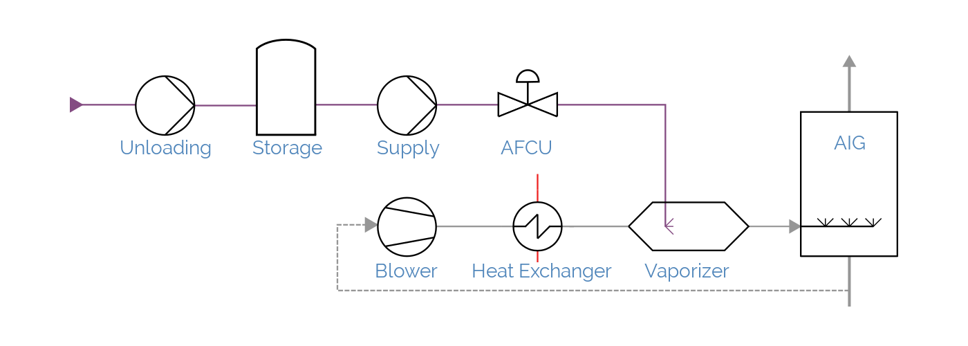
Preparation of reduction reagent aqueous ammonia $\ce{NH4OH}$For the preparation of the reduction reagent, a skid-mounted ammonia flow control unit (AFCU) is used to ensure the injection of the correct ratio between $\ce{NOx}$ and $\ce{NH3}$.
Further, a dilution air system consisting of redundant blowers and air preheater powered by steam is used. The aqueous ammonia is vaporized into ammonia by vaporizer, powered by steam. Both, preheated dilution air and the vaporized ammonia are mixed and then injected into the boiler using an ammonia injection grid which ensures the necessary homogeneity of the flue gas compounds and the injected $\ce{NH3}$. Downstream the AIG, the flue gas enters the catalyst where the chemical reaction takes place.
The main steps are vaporizing the aqueous ammonia solution, injection and mixing with dilution air and feeding to the ammonia injection grid. The following equipment is part of:
Ammonia flow control Unit (AFCU)
The ammonia flow control unit is part of the SCR system and is installed on a skid near the ammonia evaporator. The ammonia flow control unit consists out of a shut off valve, an ammonia flow metering unit and the ammonia control valve. Further the required pressure will be detected by a pressure transmitter. The required aqueous ammonia will be injected according to the deviation of the $\ce{NOx}$-set point and the measured $\ce{NOx}$-outlet value (calculated average of the flue gas streams).
Dilution air system
The dilution air system consists mainly of two redundant dilution air blowers and a steam-air-heater. The blowers are sucking combustion air from ambient air. The dilution air is heated up by the steam-air heat exchanger.
Aqueous Ammonia Evaporator
The aqueous ammonia evaporator as steam-liquid-heat exchanger, to vaporize the aqueous ammonia ($\ce{NH4OH}$) solution to ammonia ($\ce{NH3}$). Then the ammonia is injected into the hot dilution air flow and mixed with the air to get a usable medium flow to the ammonia injection grid.
Storage Systems
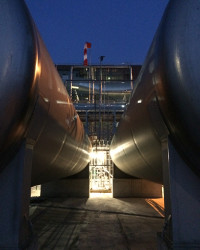
Aqueous Ammonia StorageAqueous ammonia is stored in cylindrical double wall storage tanks made out of stainless steel.
The aqueous ammonia storage tanks are designed according EN13445 and EN12952-14 and will be operated with pressure up to 45 kPa, in a temperature range from $-20^\circ\mathrm{C}$ to $+40^\circ\mathrm{C}$.
Ammonia Storage
Storage tanks
Each storage tank is equipped with
- pressure transmitter
- local temperature indication
- level indication
- level switch to protect overfilling of the storage tank
- safety relieve valve
- vacuum relief valve with flame arrester
- leakage detection system
- manhole
Computational Fluid Design
CFD studiesCFD studies
Computational fluid dynamics
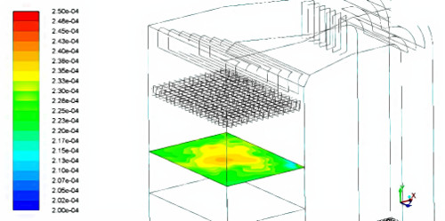
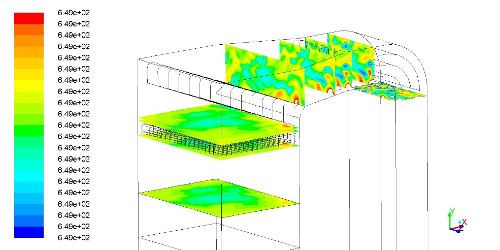
- The ammonia injection system
- Distribution of the gas flow
- Optimize the geometry and the pressure drop
- Enhance the temperature distribution in the cross-section
- Optimize the distribution and preventing the deposition of dust